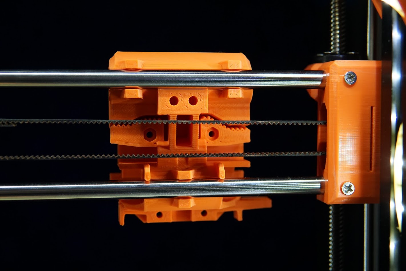
The Hotend Carriage makes use of the stock Prusa MK2s rod spacing. If you decide to use a different carriage design make sure to use a Prusa compatible one.
Note: Some pictures on this page are the older V1 extruder carriage. The improved new style MK3 carriage allows for the complete extruder assembly to be removed or installed from the X Axis rods without disassembling the Z-tower.
Start with inserting the heat-Serts into your carriage parts.

4 are inserted into the front of the X Carriage Rear Bearing Plate MK3 V2 and 2 are inserted into the back. Slowly run a screw into and out of each of these threads to ensure they align with the rest of the screw holes. It is possible to substitute these heat-serts with M3 nylocks if you have trouble sourcing them.

2 Heart Serts are inserted into the prongs on the X Carriage Front Extruder Plate MK3 V2. If you are not using a BLTouch or similar leveling probe you can skip this.
Merge these two parts together using the 2 16-20mm M3 screws into the center screw holes. Secure them on the back with 2 M3 nylock nuts.
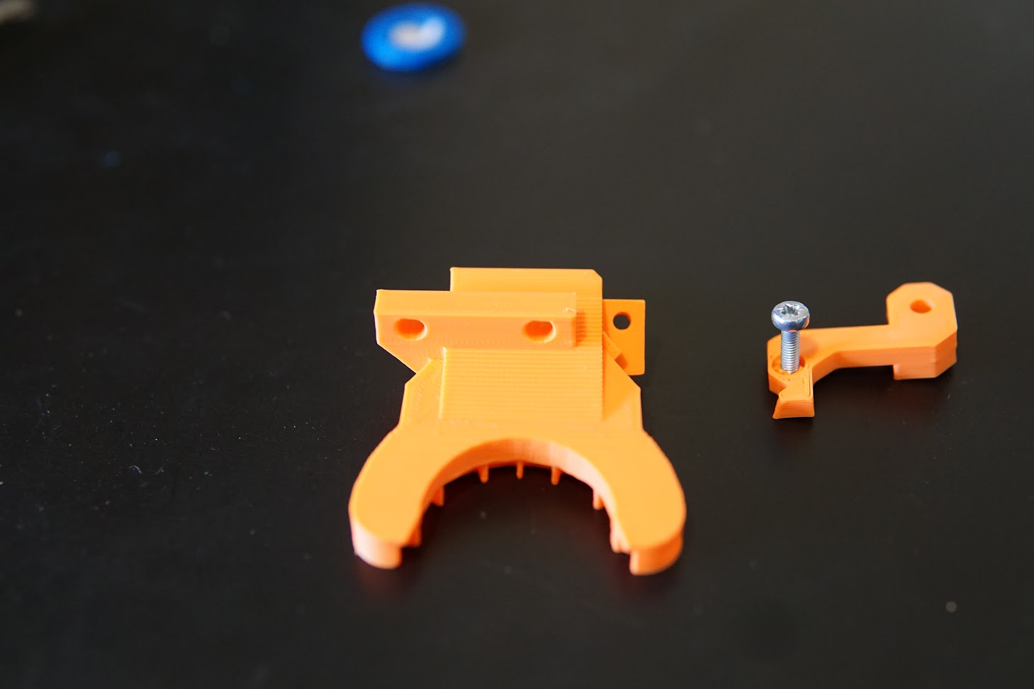
Insert 2 more heat-sert parts into the Part Cooling Fan MK3 V2. Use 2 16mm M3 screws through the bottom x carriage screw holes and into this part. Attach this to the Part Cooling Fan Bracket MK3 V2 with an M3 x 12mm screw inserted from the bottom and an M3 nylock. The Part Cooling Fan can be installed with a 30mm M4 Nut and Nylock.

Screw the Part Cooling Fan MK3 V2 to the fan bracket using 2 12mm M3 screws. Place your bearings into the carriage. This designs allows you to use 16mm M3 screws to adjust the tension on the bearing. This is very helpful for Igus bearings. I settled on 2 a combination of 2 Igus bearing and a Misumi LM8LUU to give a smooth easy and quiet movement.
Install the extruder motor, extruder and extruder plate.


Once completed this carriage should be significantly lighter than the original. The original carirage came to 620grams.

This new design comes in at 430gramms, around 190grams lighter.

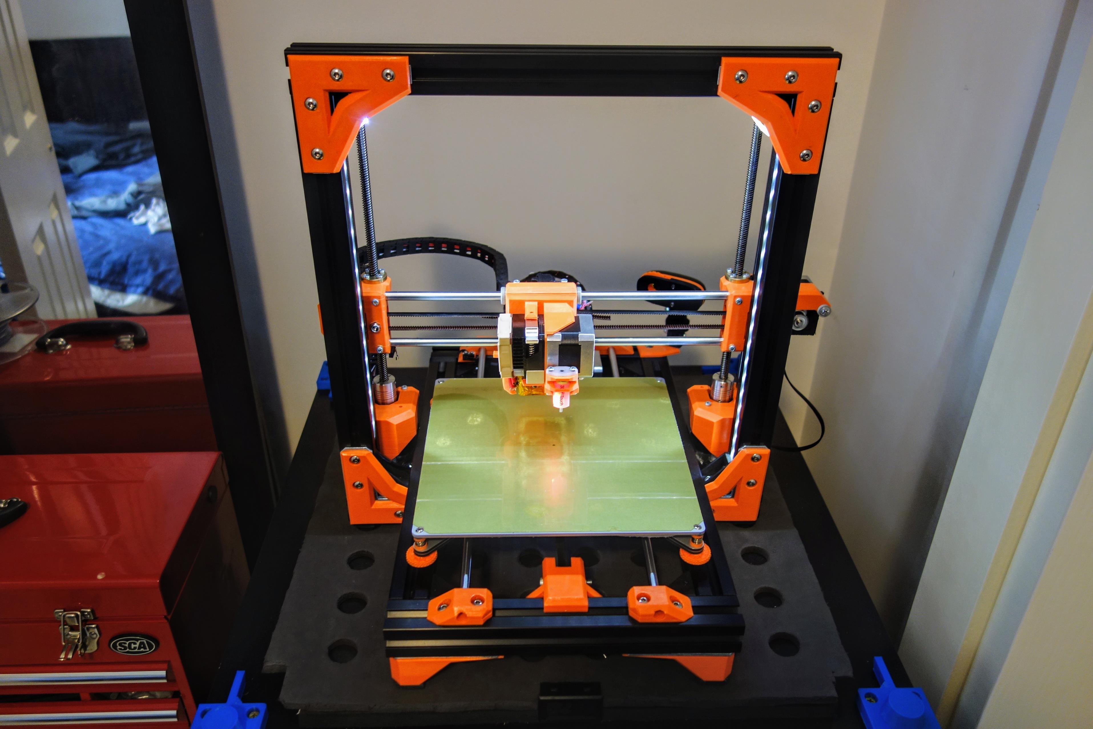
Continue to assemble the X-axis gantry.
Z Probe Offset values for marlin configuration
#define X_PROBE_OFFSET_FROM_EXTRUDER 24
#define Y_PROBE_OFFSET_FROM_EXTRUDER -36