Now that the x gantry is installed the rest of the frame can be completed.
Attach the final 380mm crossbeam horizontally to the 355mm tower parts. On the front side attach using 12mm M5 screws into the Tower Corner Bracket Large then the plate bracket. Also attach a 30x30 corner bracket and secure it with 12mm M5 screws.
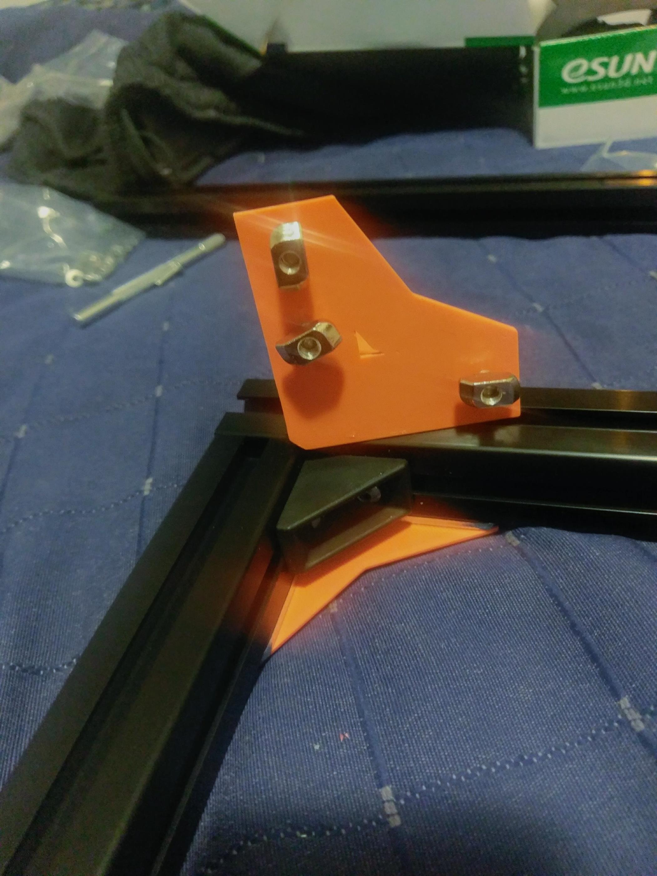
On the backside (where the rods are) use the Z Axis Rod Top Left Bracket and Z Axis Rod Top Right Bracket parts. Each of these requires a heat-sert into the space near the smooth rod hole.
mount each of these with 12mm M5 screws while also securing the smooth rod.

Use a 16mm 3M screw into opposite side from the heat-sert hole to secure the threaded rod.

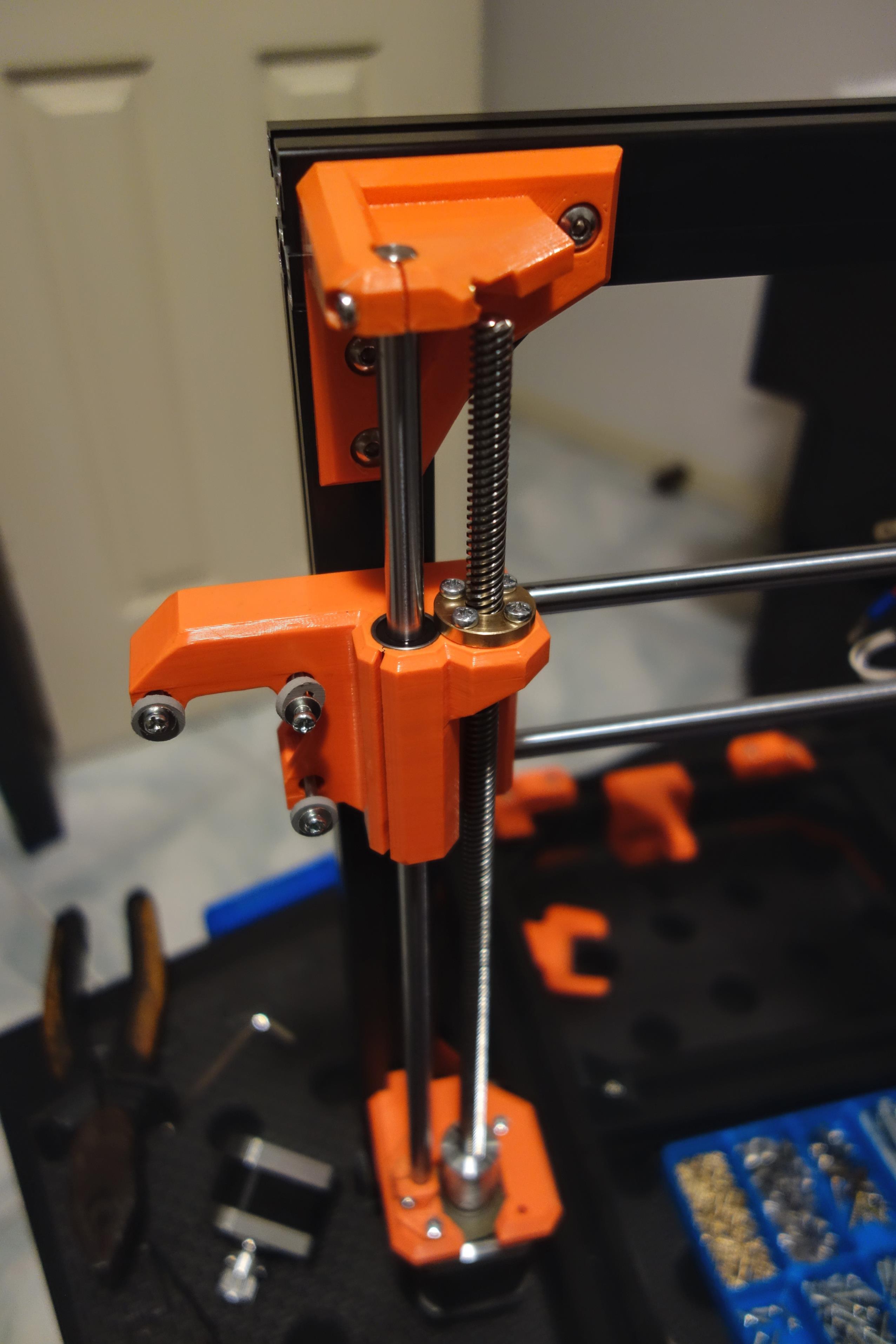
The printer should now look similar to this.
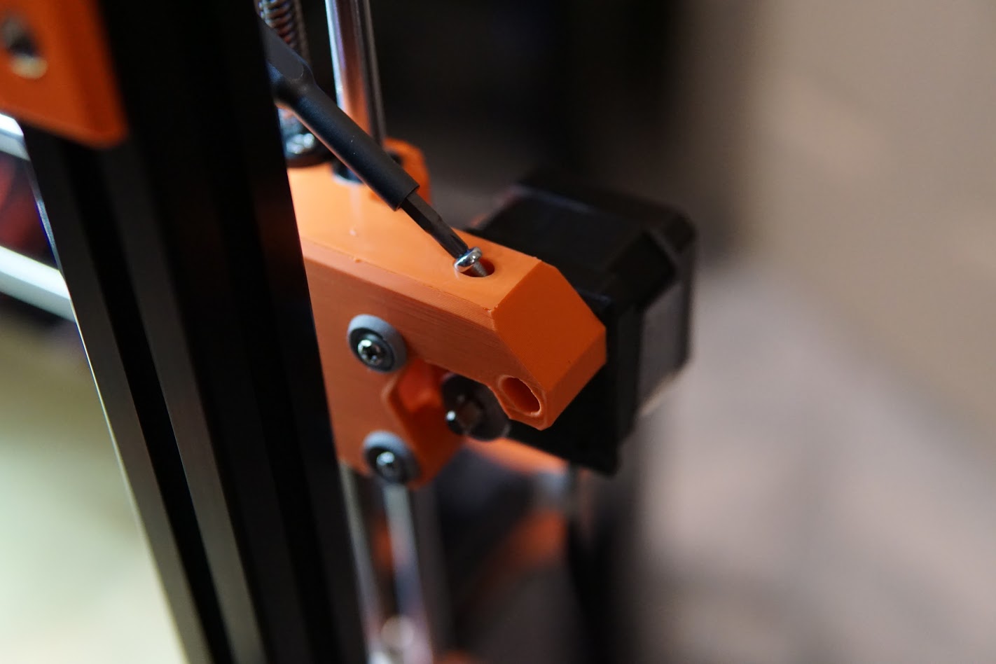
Install the M3ns nut (thin m3 nut) into the X Gantry Motor Mount MK3 V2 and lightly install a 20mm m3 screw into the hole on the top.
Install the belt into the X Carriage while the X motor is rotated inward. Give it sufficient tension then rotate the X motor to increase the tension in the belt and tighten the 3 screws.
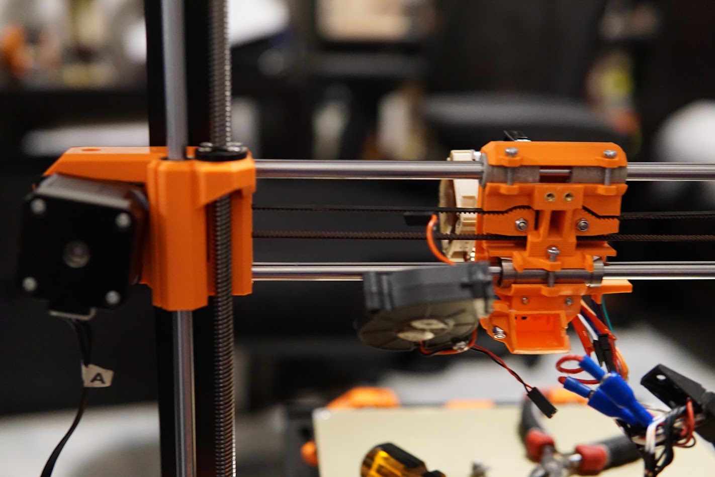
Screw in the M3 screw on the top of the motor mount to completely rotate the Motor and increase the belt tension.
The tensioning process can be done by referring to the Prusa MK3 manual Steps 11-18.
Next complete the Y-axis.